Fracture Behaviour: In-Situ SEM of Microbeam Bending
Fracture behaviour of aluminide bond coat – new application note from Hysitron. An in-situ study of microbeam bending.
Contact us about nanomechanical testing
View our range of scientific instruments
Fracture Behaviour: In-Situ SEM of Microbeam Bending
In this study, the Hysitron PI 85 SEM PicoIndenter was used for in-situ bending tests on microbeams in a PtNiAl bond coat material. By providing quantitative load-displacement data coupled with SEM imaging, the fracture toughness and cyclic fatigue behaviour of the bond coating were determined.
Bond Coats
Bond coats are heterogeneous and microstructurally complex diffusion layers. They are applied to superalloys to provide high-temperature oxidation resistance to the substrates. The coatings, commonly made of (PtNi)Al by a pack aluminisation process, are constantly subjected to thermal stress, mechanical fatigue, phase transformations and erosion by particle impact.
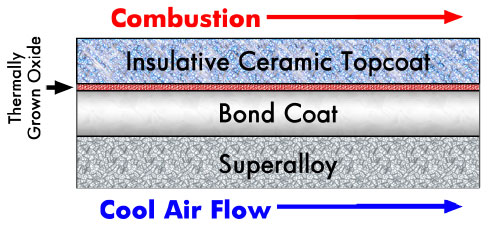
A typical turbine blade cross-section, showing the metallic superalloy substrate, a metallic bond coat, thermally grown oxide, and a thermally insulative ceramic topcoat.
Doubly-Clamped Beam Bending
This study demonstrates a new technique for measuring fracture toughness of a specific micro-structural zone within the bond coat layer, using microbeam bending. This technique has advantages over indentation-based and macro-scale fracture toughness measurement. The properties of the different micro-structural zones within the bond coat region can be isolated, without any convolution of the measurement by adjacent zones or underlying substrate.
Experiment Method
- Double clamped microbeams, 100 μm X 10 μm X 8 μm (length, width, height) were fabricated using FIB from Zone A within the bond coat.
- A small notch was milled in the center-bottom region of the beam for a controlled crack initiation.
- The sample was mounted on a PI 85 SEM PicoIndenter equipped with a wedge tip for bend testing.
- Load-displacement data and the real-time video of micro-structural changes were synchronised and captured during each test, which aided the post-experimental analysis.
Beam Bending
The figure below shows a representative force versus displacement curve from monotonic beam bending tests. For this test, the load is shown to increase linearly until ~7 mN, at which point a large displacement burst occurs. Through analysis of the synchronised video, it is determined that this displacement burst corresponds to the initiation of a crack emanating from the tip of the pre-notch and propagating towards contact point with the wedge probe. Using the recorded force-displacement data along with a pre-existing XFEM model for beam deflection, the fracture toughness was calculated to be 16 MPa-m1/2.
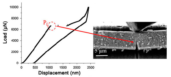
Load-displacement data from a bend test, along with an image captured from the synchronised live video at the moment of fracture initiation.
Fatigue Loading
The results from the constant-load fatigue test are below, where the beam was cyclically loaded to ~85% of the critical fracture load. The top set of data demonstrates the highly elastic behaviour of the microbeam after the first load-unload cycle to the sub-critical peak force. The bottom set shows the data acquired through the fifth loading cycle, at which point analysis of the load-displacement data and synchronised video confirmed that catastrophic failure had occurred.
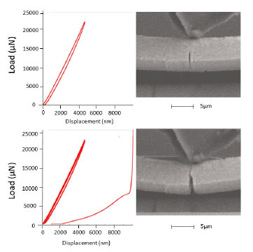
Results from the single-force fatigue cycling of a PtNiAl microbeam.
Toughening

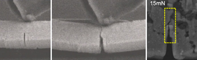
The results from cyclic/fatigue loading tests at progressively higher loads.
- Fatigue loading shows stable crack growth with increasing load.
- The crack-length increases in the first cycle at a given load but doesn’t propagate in the next 49 cycles under the same applied loads.
- Load-displacement data shows that stiffness doesn’t change much at a particular load. However, stiffness decreases with increasing load.
- In-situ tests were able to provide evidence of crack growth and arrest, resulting in an overall toughening response.
- Toughening mechanism in zone A involved crack bridging by α-Cr precipitate particles.
If you have any questions about nanomechanical testing, or whether in-situ SEM would be suitable for your research, please contact us on 01223 422 269 or info@blue-scientific.com