Tensile and Compression Testing with Micro-CT Imaging
In-Situ Tensile and Compression Testing
How to image your samples during compression and tensile tests, using X-ray micro-CT and specially designed material testing stages.
Blue Scientific is the official UK distributor for Bruker Micro-CT. For more information or a quote, please get in touch:
Contact us on 01223 422 269 or info@blue-scientific.com
Micro-CT Instruments
Observe Changes in Your Sample
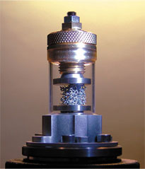
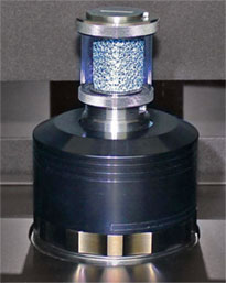
Study changes in your sample’s micro-structure when pressure is applied, using mechanical testing stages. With 3D internal imaging, you can observe the results in-situ, inside your micro-CT scanner. During scanning, the sample is subjected to a controlled load and the loading curve is displayed on the screen in real time.
Stages are available for all Bruker micro-CT systems. They can be installed easily in place of the standard sample holder, and are controlled using dedicated software, compatible with the main scanner control programme.
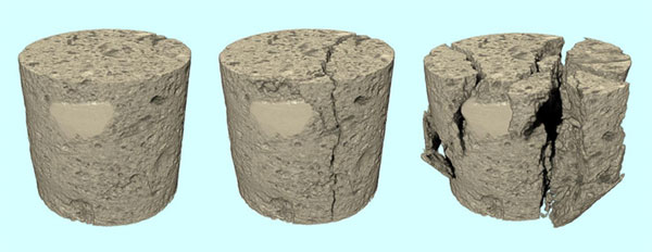
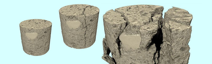
Micro-CT shows clearly how compression affects Noyant limestone. 9.5 mm diameter sample, scanned using the Bruker SkyScan 1275 with 12.1 µm pixel size.
How it Works
An accurate force, measured by a load cell, is applied to the sample. The resulting deformation is measured by a precision displacement sensor. There are two modes:
- Continuous mode – Compression or tension up to a maximum allowable load or until the maximum displacement.
- Predefined mode – Up to a specified load or displacement.
The loading curve is displayed on screen in real time. All load/displacement and stress/strain curves can be displayed and saved. The object can also be held under a specific single or multiple loading during imaging.
If required, the load cell can be changed to a different range. However, it is important to remember that the accuracy of the measurement is around 1% of the load cell’s full scale. The load cell’s range should be high enough for the load required, but an “oversized” load cell will negatively affect the system’s sensitivity. It’s also important to note that the load cell is installed and calibrated in the factory and cannot be replaced in the lab.
Material Testing Stages
In addition to the models below, special stages are also available for micro-positioning, cooling and heating.
MTS1
Compatible with Bruker SkyScan 1072, 1172, 1173 and 1174
- Compression and tensile testing
- Factory calibrated load cell and linear displacement sensor
Specifications:
- Maximum force: 44N, 220N, 440N
- Displacement sensor accuracy: ± 0.01mm
- Load measurement accuracy: ± 1% of the full range
- Maximum object diameter : 20mm
- Maximum travel: 5.5mm
- Max object height for compression: 23mm
- Max object length for tensile tests: 18mm
MTS2
Compatible with Bruker SkyScan 1272, 1275 and 2214.
- Symmetrical load from top and bottom, keeping the central part of the object static
- Compression and tensile testing
- Factory calibrated load cell and linear displacement sensor
Specifications:
- Maximum force: 44N, 220N, 440N
- Displacement sensor accuracy: ± 0.01mm
- Load measurement accuracy: ± 1% of the full range
- Maximum object diameter : 20mm
- Maximum travel: 11mm
- Max object height for compression: 24mm
- Max object length for tensile tests: 20mm
MTS3
Compatible with Bruker SkyScan 1272, 1275 and 2214
- Compression testing
- Factory calibrated load cell and linear displacement sensor
Specifications:
- Maximum force: 2200N, 4400N
- Displacement sensor accuracy: ± 0.01mm
- Load measurement accuracy: ± 1% of the full range
- Maximum object diameter : 22mm
- Maximum travel: 5.5mm
- Max object height: 20mm
How to Get the Best Results
As with stand-alone testing stages, correct sample preparation and mounting is important for the best results:
The force required depends on sample dimensions, so this is an important factor to consider when choosing a materials testing stage. The accuracy is also related to the maximum force of the load cell (typically 1 %).
It is important to maintain good contact between the load area and the sample. This can be ensured in various ways, depending on the sample type, for example:
- Flattening the contact surfaces (eg for compression testing of rocks)
- Using grip improving spacers
- Gluing samples with epoxy resin
The recommendations for selecting scan parameters are very similar to when running a regular scan. Sample stability is key; this may involve allowing time for sample relaxation before starting the scan at a certain load point.
With Bruker micro-CT material testing stages, samples can be loaded in manual mode or automatically, with a predefined load or displacement. ‘Scheduled scanning’ mode enables further automation by scanning at different loading points.
Application Notes
Further information is available in these application notes, available on request:
- MN049 – Compression testing of trabecular bone in the Materials Testing Stage (MTS)
- MN097 – Compression testing of Noyant limestone with the MTS3
For more information about Bruker micro-CT and testing stages, please get in touch: