How to Test Micro-CT Spatial Resolution
Micro-CT Spatial Resolution Testing
How to test the spatial resolution of your micro-CT scanner in 2D and 3D, and the factors that can affect resolution.
Blue Scientific is the official distributor of Bruker Micro-CT systems in the UK. The range includes benchtop scanners and advanced research systems. For more information or quotes, please get in touch:
Micro-CT instruments
Contact us on 01223 422 269 or info@blue-scientific.com
Testing Micro-CT Resolution
Over the years, several different methods have been used to assess the performance of micro-CT instruments. Typically, the limiting factor at high resolution has been the focal spot dimensions. Tests often rely on determining the spot size from 2D projection images only.
The true 3D spatial resolution depends on many factors, including:
- Mechanical accuracy of the instrument.
- Temporal stability – extremely important for 3D scans, which have a longer duration than 2D.
- Processing and reconstruction algorithms also affect the spatial resolution that can be achieved.
3D Spatial Resolution
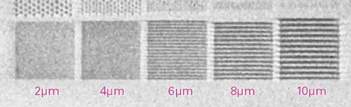
3D spatial resolution can be measured using the Micro-CT Bar Pattern NANO Phantom from QRM GmbH. The phantom has two silicon chips in orthogonal positions, with resolution test patterns from 1 – 10 μm. An application note is available, explaining how to use it with a walk-through of the procedure using the SkyScan 1275 – please contact us if you’d like a copy.
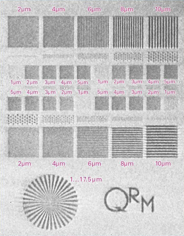
Bar Pattern NANO Phantom – Reconstructed slice from a scan taken with Bruker SkyScan micro-CT at an image pixel size of 2.8 μm.
ASTM E 1695-95
Alternatively, ASTM E 1695-95 includes a test method that involves scanning a uniform cylindrical test object, such as an aluminium pin. The 3D spatial resolution can be calculated with a modulation transfer function. The contrast sensitivity can also be calculated.
2D Spatial Resolution
Edge unsharpness can be determined through careful evaluation of the transmission profile through a test object, such as a ball or crossed wires from W alloy or Pt. The spot size can then be calculated. This method is described in EN 12543-5:1999, or ASTM E 2903-13 for 5 – 300 µm spot sizes.
For higher resolution instruments, the focal spot size can be calculated by analysing the modulation transfer function from line or star patterns. Line patterns in the range of 0.1 – 10 μm and 0.4 – 15 μm are available on JIMA resolution charts RT RC-04 and RT RC- 02B.
If you have any questions or if you’re looking for a high resolution micro-CT system, please get in touch for advice:
Bruker Micro-CT
Contact us on 01223 422 269 or info@blue-scientific.com
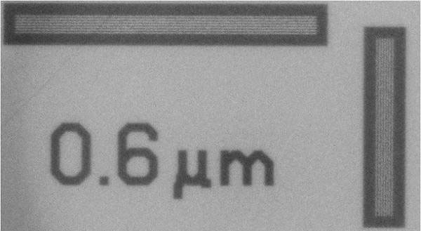
Projection image of MicroChart JIMA RT RC-02B taken using multi-scale X-ray nano-CT.